Ever Forward!...with the flashlight project.
The resistor sampler pack arrived today and I'm already scratching my head for the best way to store the spindly things. OCD tendencies aside, the pack included a set of 10 ohm resistors. When plugged into my circuit, these seem like they fit the ticket for getting a max light output without resulting in overheating components. Cool, now I just need to test the voltage across the circuit and make sure I'm not expending too much power on the LED for diminishing returns in light gain. (A reminder that I don't know what I'm doing, so my electrical engineer readers should feel free to correct errors in my thinking.)
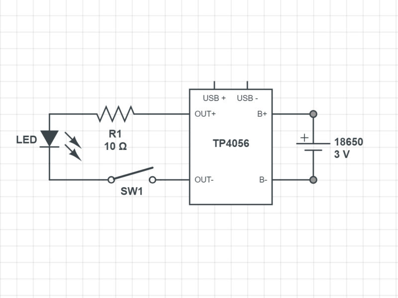
I went ahead and put together a circuit diagram for the project, courtesy of "Circuit Lab." As you can see, the TP4056 is pretty much the heard of the circuit. I haven't yet power cycled the whole thing and compared to the spec sheet to check my understanding of what that guy does.